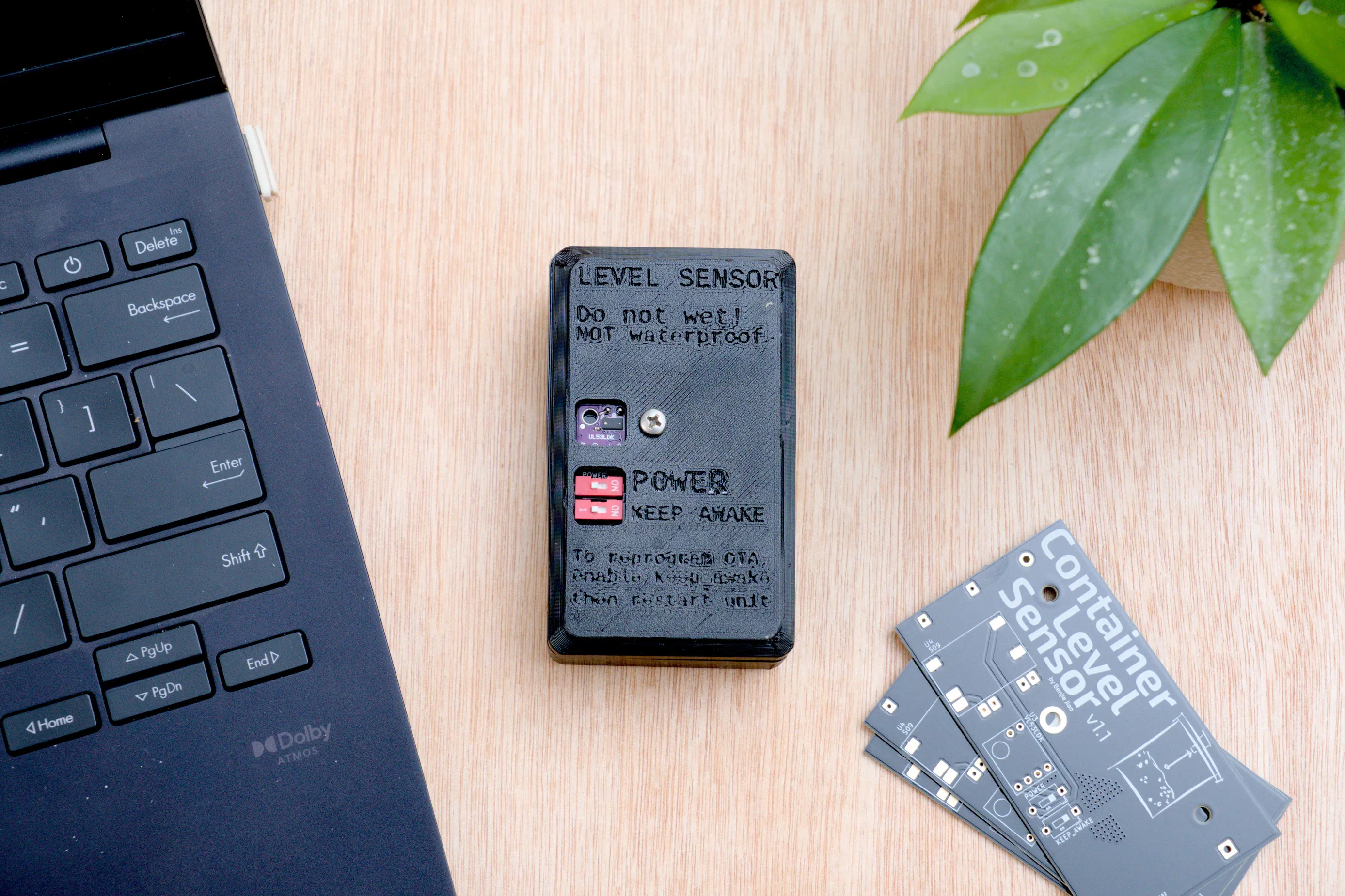
The Problem
My wife and I take care of 40+ rescued cats at home. With this comes the need to closely monitor supplies like cat food and litter. I thought it would be nice to have a way to automate the process and give us better operational awareness.
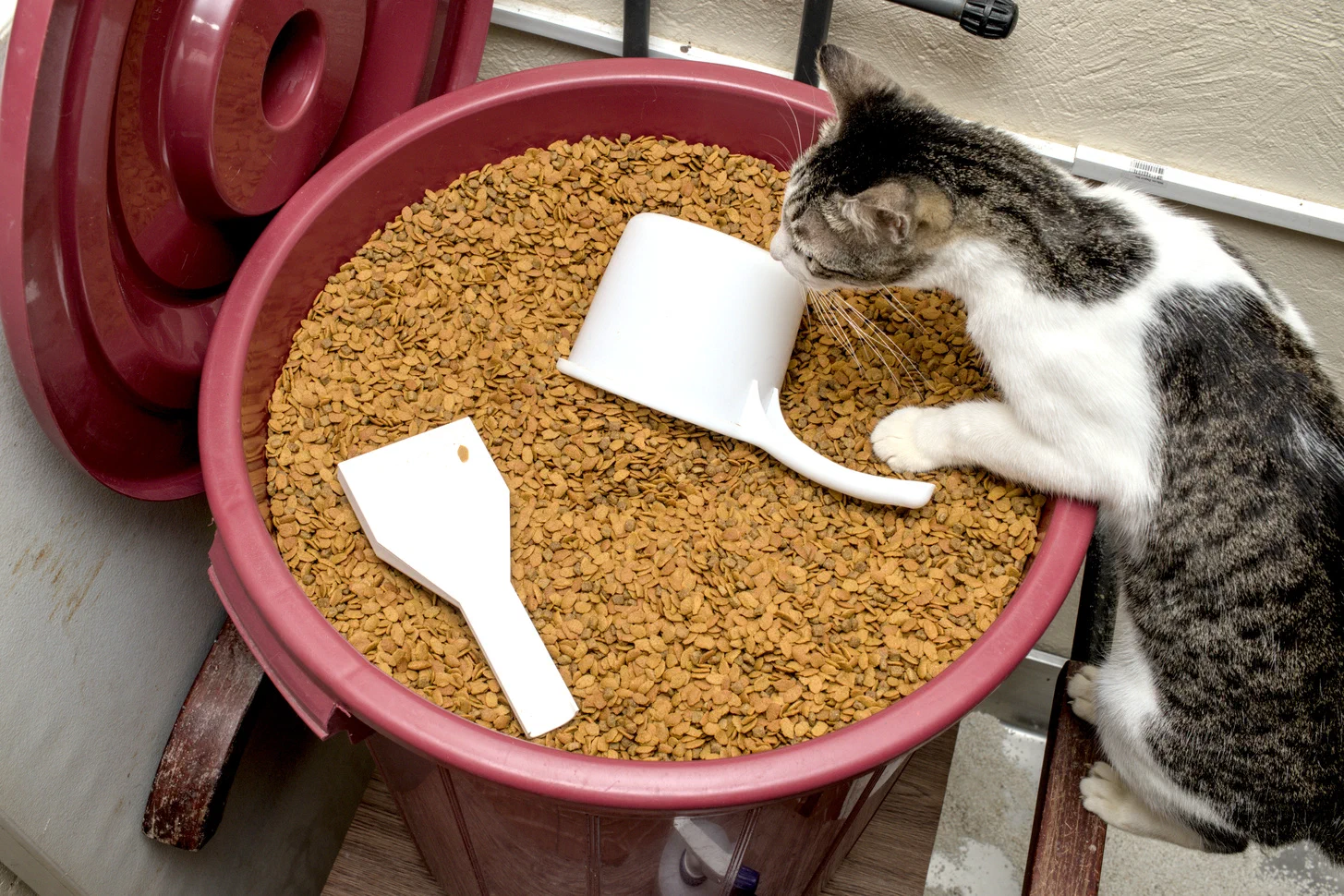
I’ve also been wanting to share more of my non-synthesizer related electronics projects so here we go…
The Idea
The idea was to design a device that would let us keep track of our cat food and litter levels and would alert us if any of these are running low. The plan was to:
- Mount the device on the lid of the container, with the sensor pointing down.
- Calibrate the software to identify how far the bottom of the container is from the sensor.
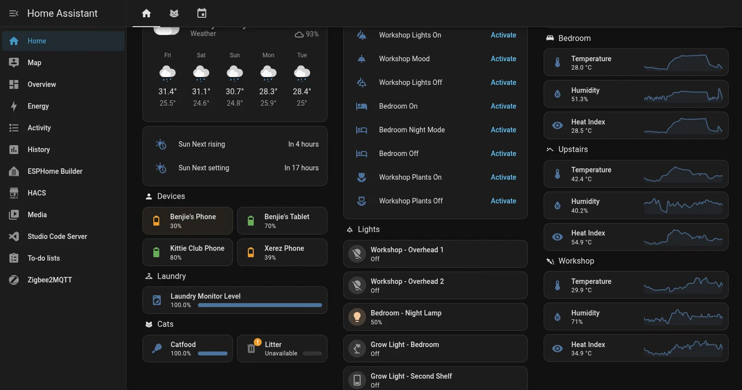
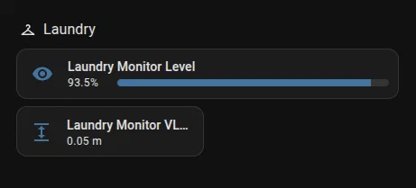
- Display the current state of the container on a HomeAssistant dashboard. Alerts will also be possible through HomeAssistant.
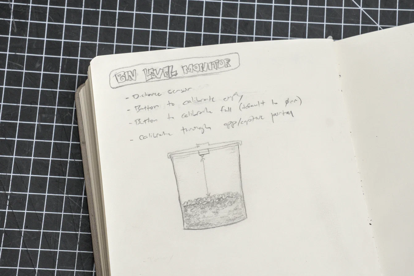
I didn’t want to expose the device to the cats, so I thought I’d mount it from the inside of the lid.
Of course, you should be able to use this to keep track of things other than cat food. You’ll see later that I actually use it to keep an eye on our laundry basket.
I’ve already been using HomeAssistant and DIY climate sensors to keep track of temperature and humidity around the house, so it just makes sense to add these new things to the same dashboard.
Prototyping Journey
Breadboarding
I already had ESP32-C3 Super Mini’s in stock, so I went with those. I like how tiny they are and I also like how you could update them wirelessly over wifi.
For measuring distance, I went with the VL53L0X time of flight distance sensor. It works by shooting an infrared laser pulse and then measuring how fast it reflects back to the sensor. It has an effective range of about 1 meter – which is alright for monitoring a tub of catfood which is about 500cm. I also picked this over ultrasonic sensors because these, in theory, have better precision.
The MCU and the sensor, along with a bunch of jumper cables, were enough to build a breadboard prototype.
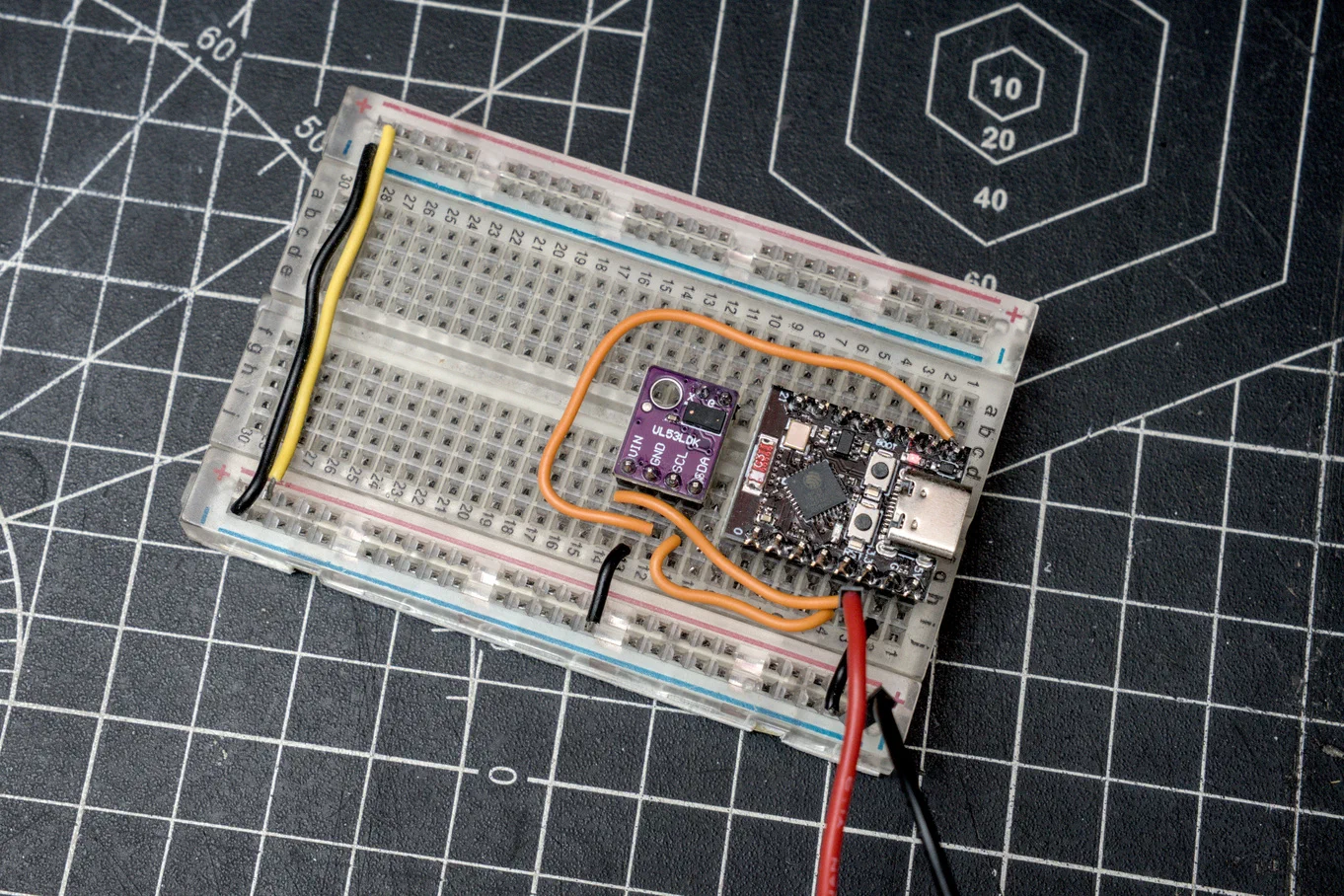
I programmed this using the ESPHomeBuilder plugin in HomeAssistant. Preparing the device was as simple as plugging in the ESP32-C3 through USB, clicking New Device, and then waiting for it to flash a basic firmware.
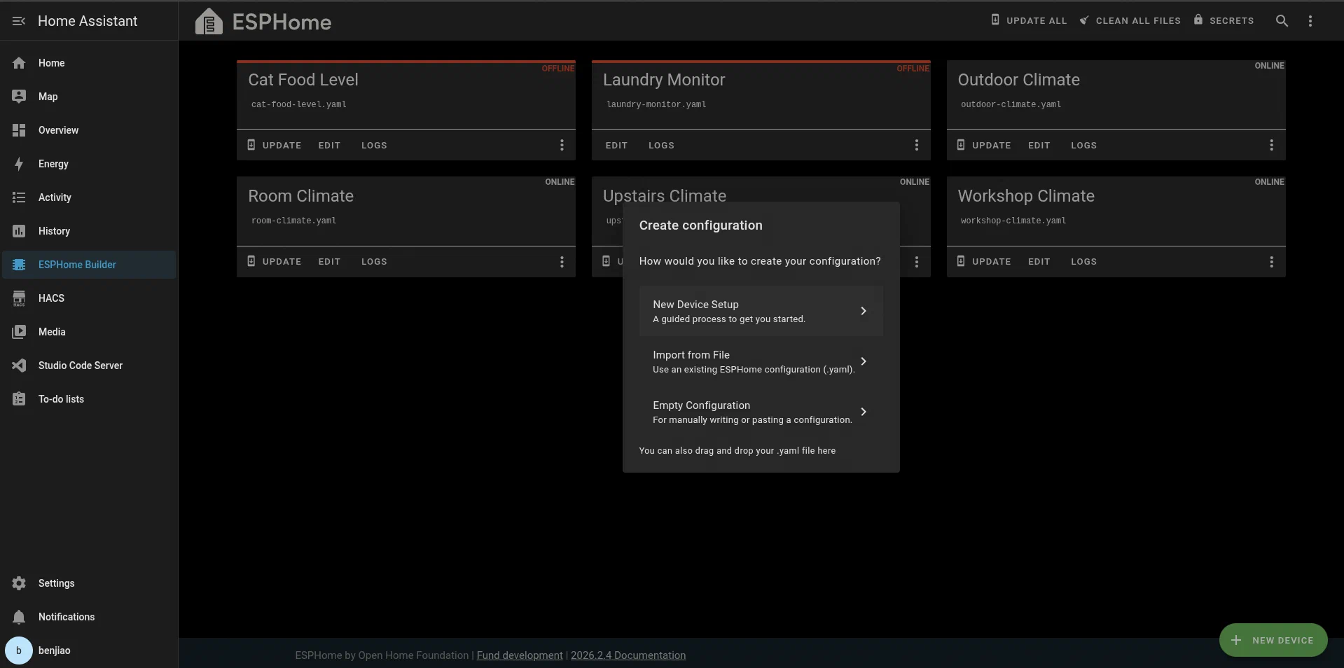
The initialization step configures the ESP32-C3 to connect to a WiFi AP. From there, you should be able to install firmware wirelessly.
WiFi Issues
I ran into a problem where the ESP32-C3 couldn’t connect to my WiFi access point. It got fixed after I switched power source from my PC’s USB port to my UGreen USB-C dock. I assume my PC’s USB port had power issues and that was causing the WiFi antenna to be spotty.
Perfboard Prototype
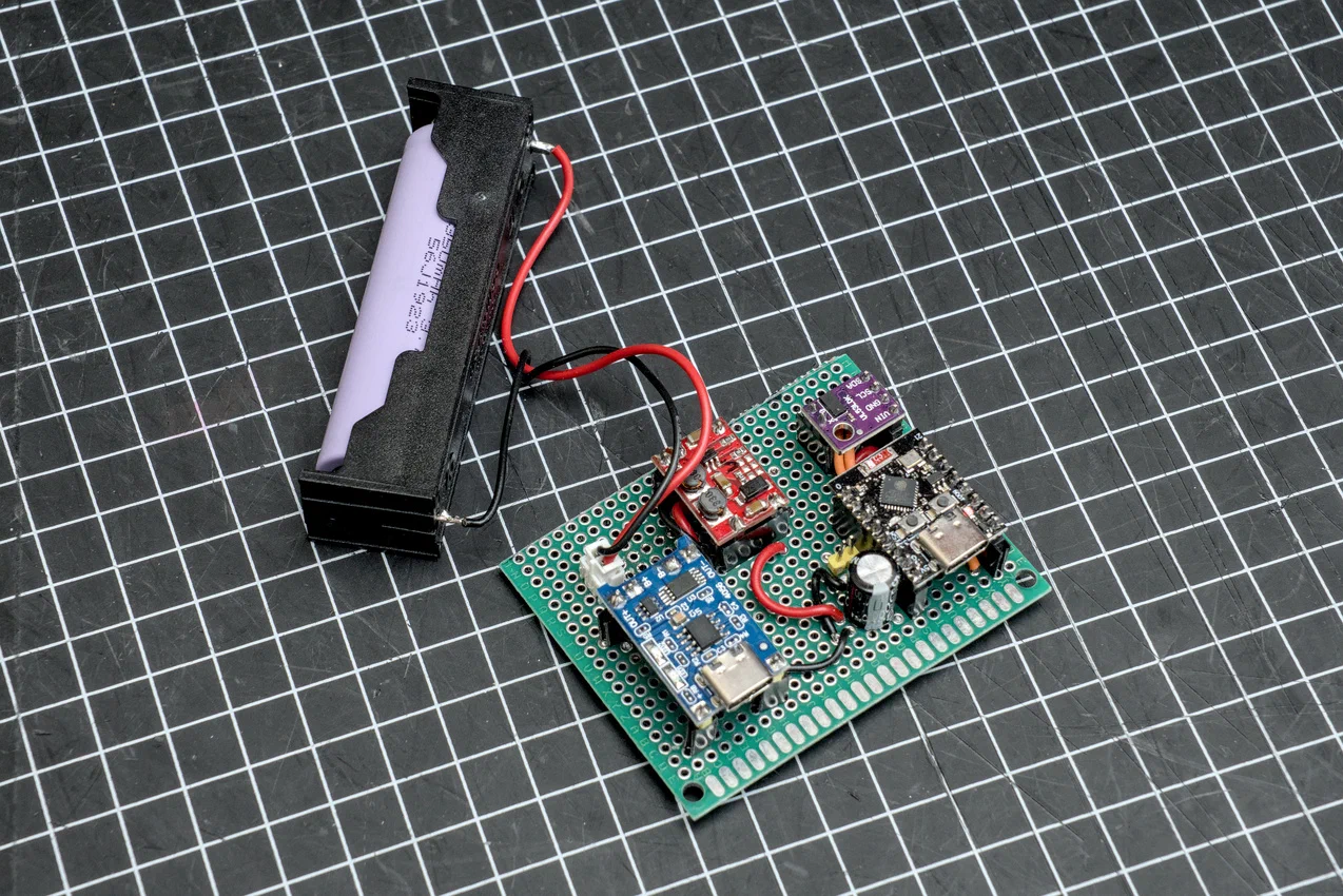
WiFi started to become spotty again when I started testing the battery module, so I decided it was time to build this on a perfboard. I figured I might be getting some loose connections or voltage drops from the breadboard and the ESP32-C3’s 3.3V needs a somewhat clean power source.
Battery Life and Deep Sleep
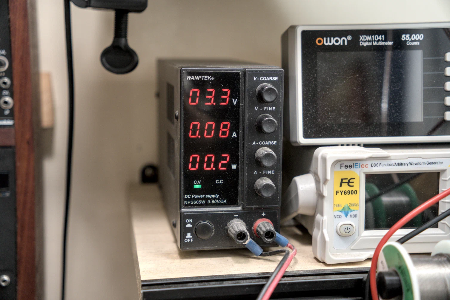
I tested the circuit on my bench PSU and got 80mA reading. With a 3000mAh battery, this meant that I only had around 24hours of total run time, which was unacceptable. I don’t want to charge the thing daily. I might as well just check the catfood level every day. (Wait… do I even have to do this project? Kidding, of course I do!)
I looked into the ESP32’s Deep Sleep feature. This way, I can run the sensor for 1 minute, send data to the server, and then sleep for 1 hour. With this strategy, I expected the battery life to last for months, and I was right — in my initial run it took 133 days (about 4 1/2 months) before my laundry sensor needed charging.
In the future I could probably get even more battery life by switching to a Zigbee-based connection, which requires much less power than WiFi. I’m also considering running it once a day instead of hourly, since I don’t really need realtime updates.
Maintainability
It will be impossible to do updates over WiFi when the sensor is in deep sleep. I needed to add an “awake” pin that kept the ESP from going into Deep Sleep while I sent updates wirelessly.
I decided to go with GPIO3.
A restart was necessary for the ESP to recognize any changes to the awake pin. So for updates, the flow would be:
    flowchart TD
    a[Turn off module]
    b[Turn on awake pin]
    c[Turn on module]
    d[Send OTA updates]
    e[Turn off module]
    f[Turn off awake pin]
    g[Turn on module]
    a --> b --> c --> d --> e --> f --> g
PCB Design
First Enclosure
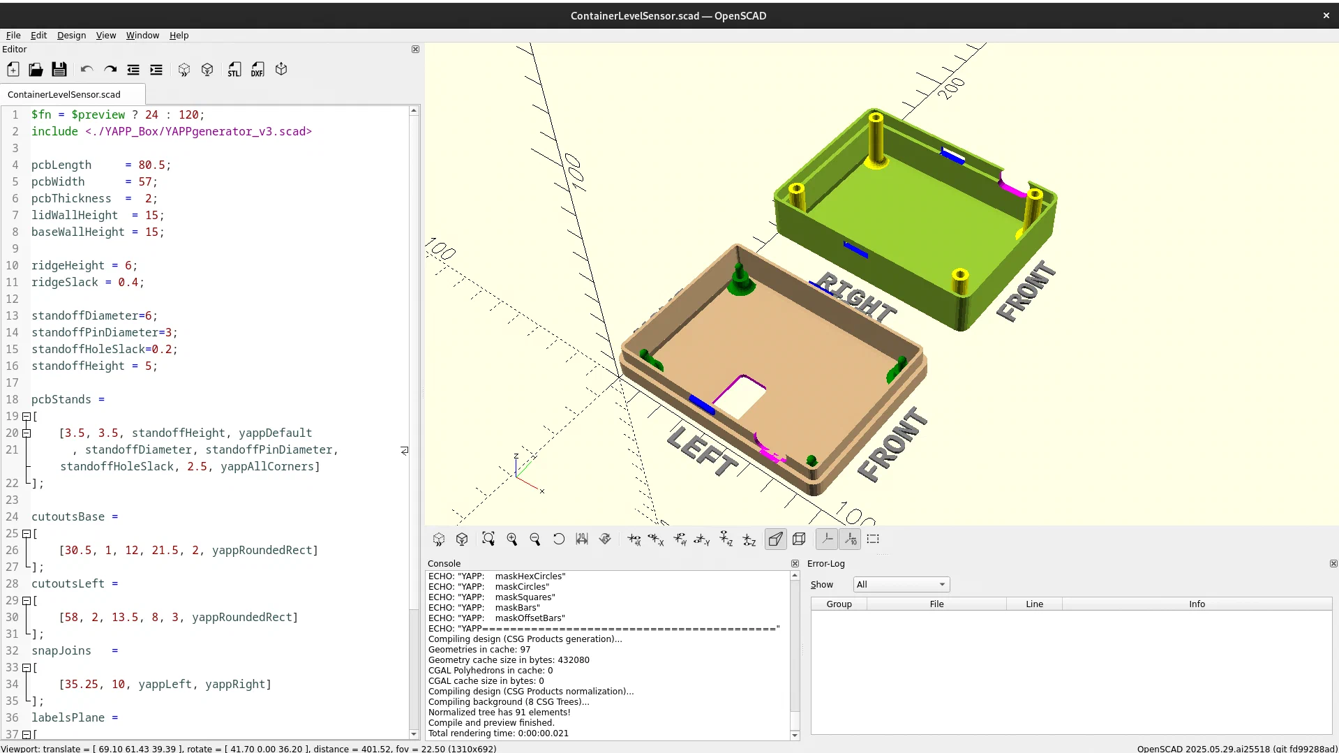
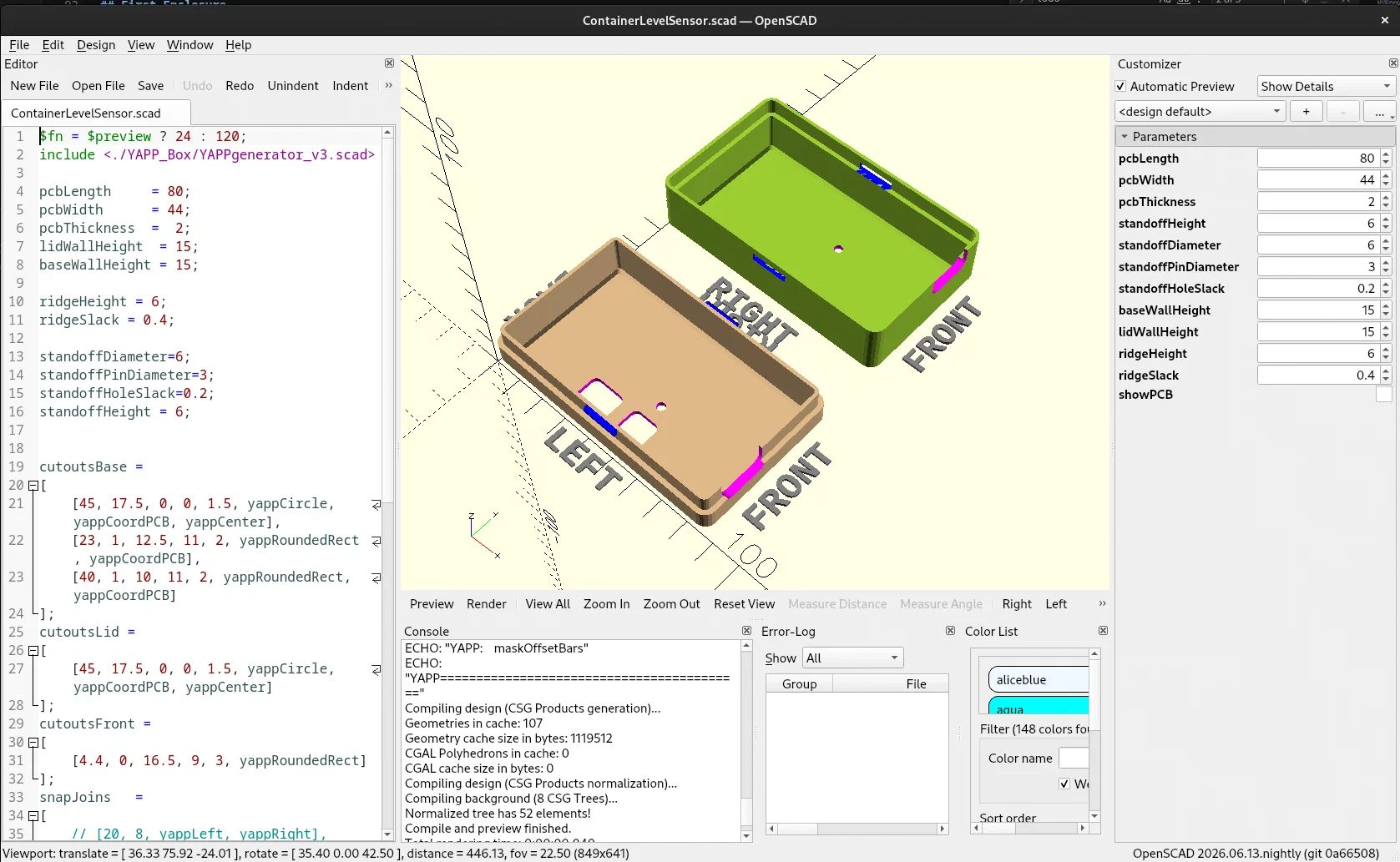
I designed the enclosure for this in OpenSCAD with the help of YAPPgenerator library. It’s a quick way to design boxes especially for PCB-based projects.
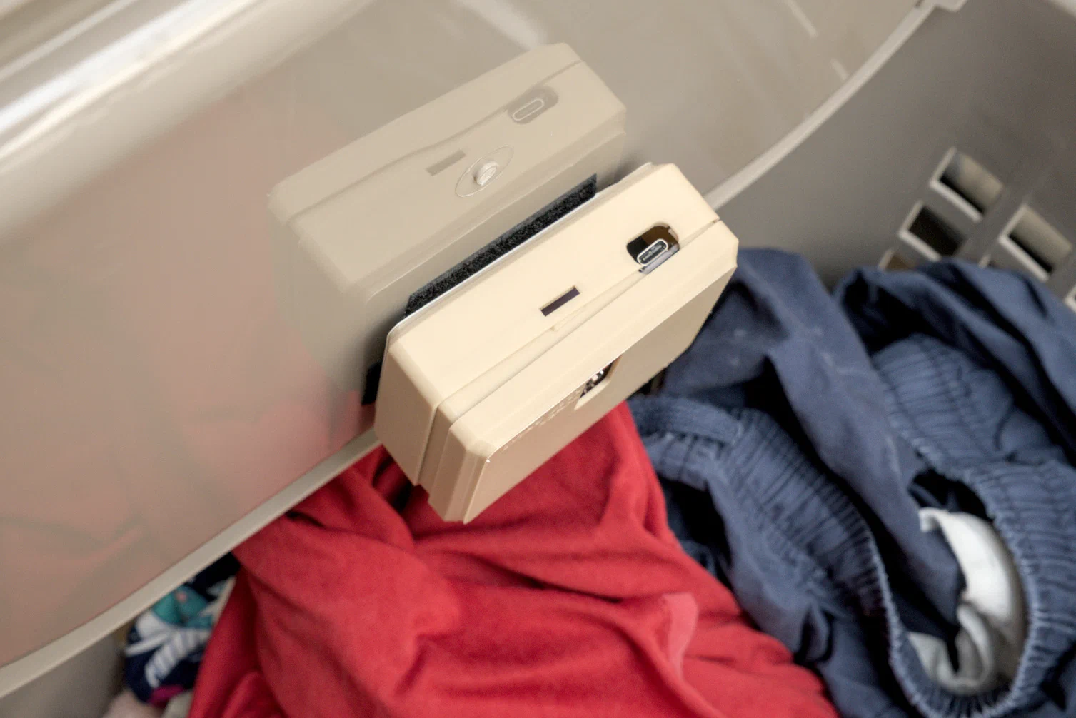
I decided to test this on our laundry basket first. I used adhesive-backed velcro to mount it to the lid temporarily.
It held up pretty well, except the snap-on case started falling apart. It would frequently come apart from all the closing.
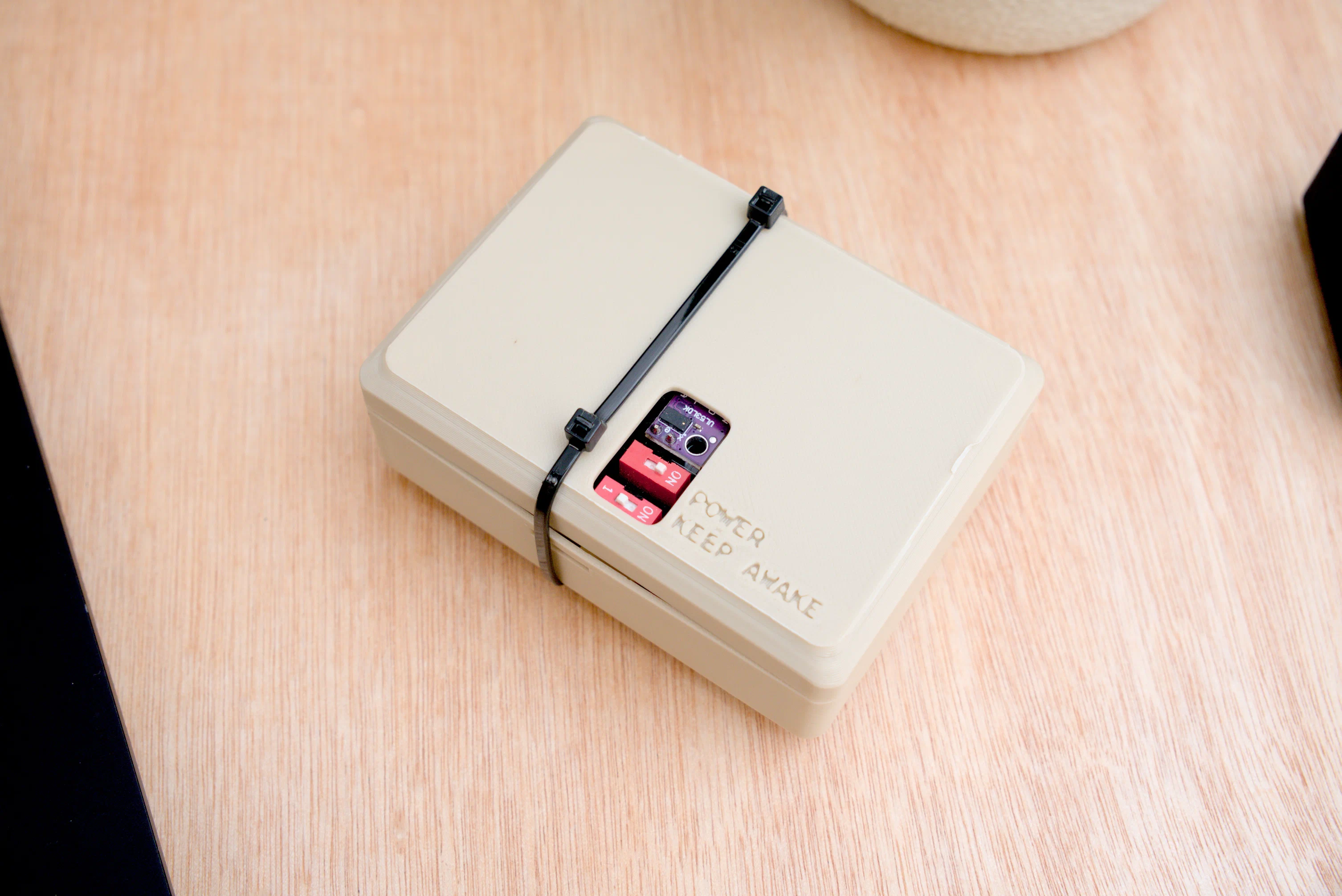
I used a ziptie as a quick fix.
The Final Design
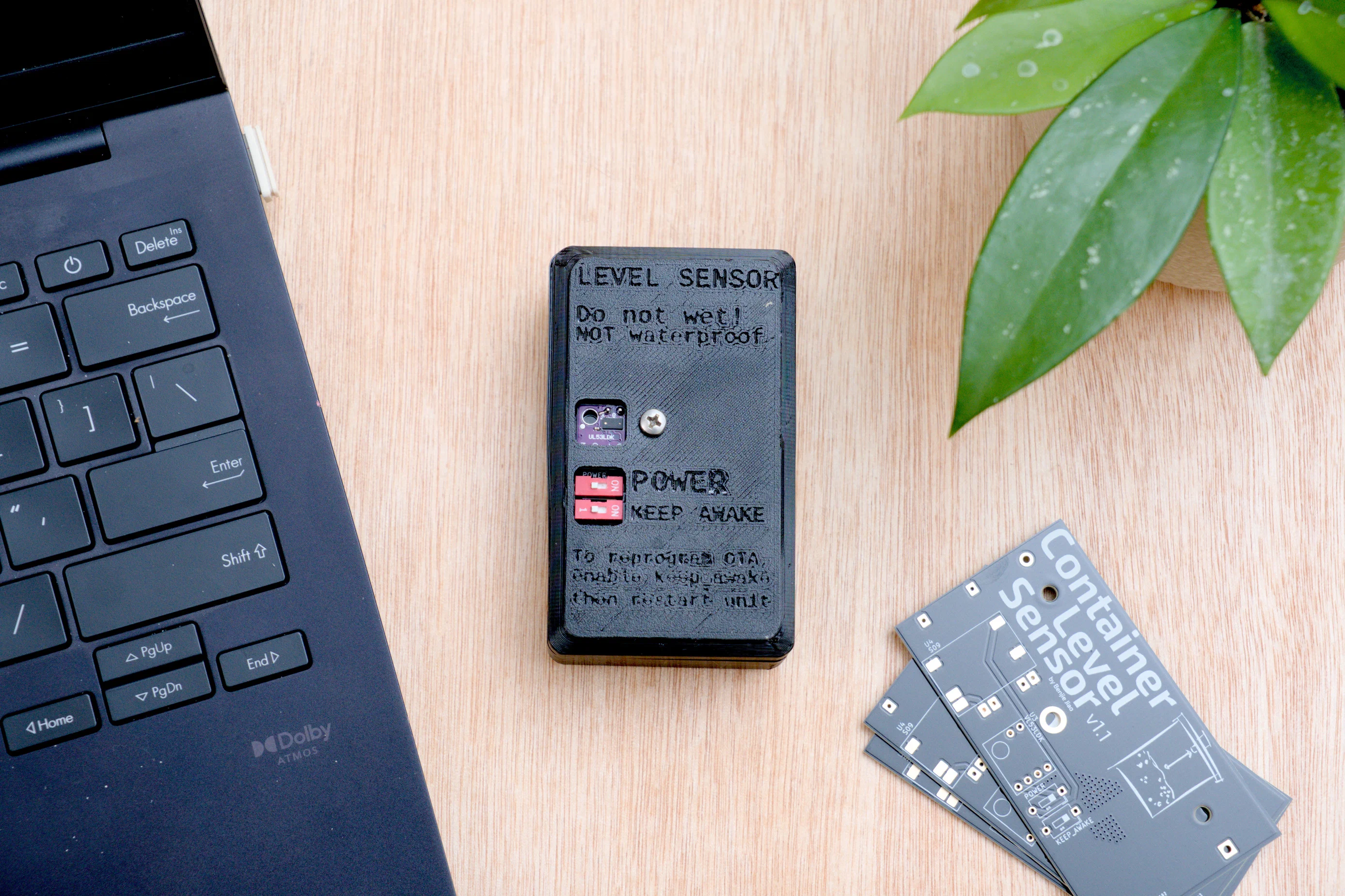
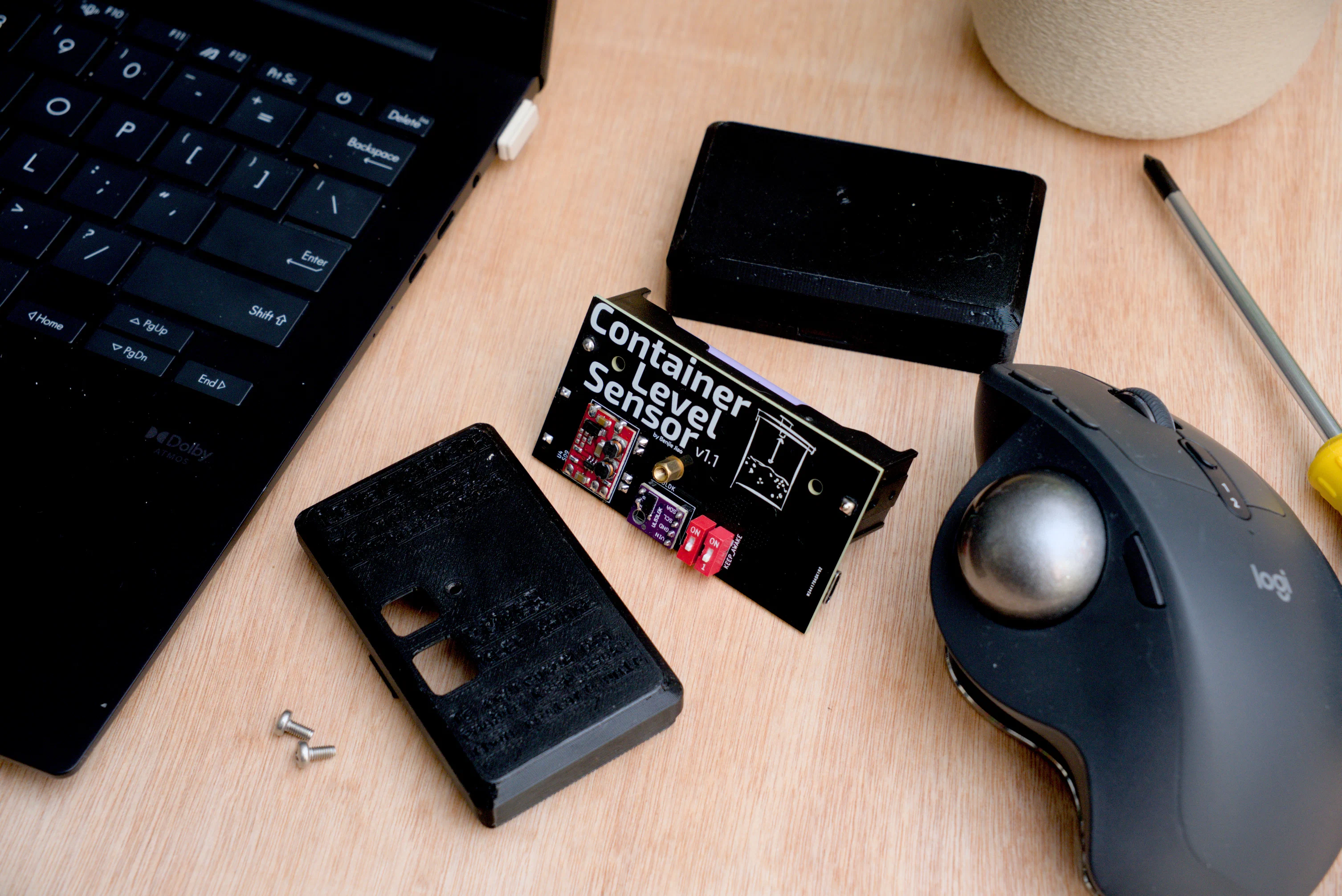
The final design that I came up with has a smaller footprint. I also improved the mounting solution to use screws to hold everything together.
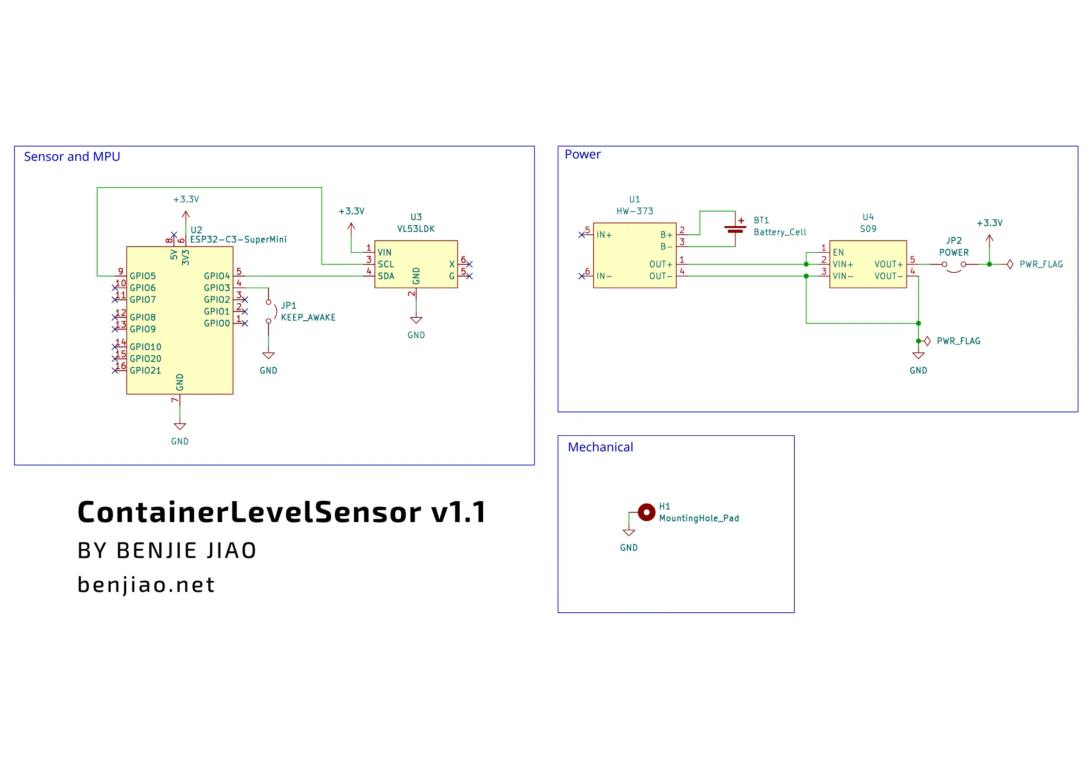
Circuit
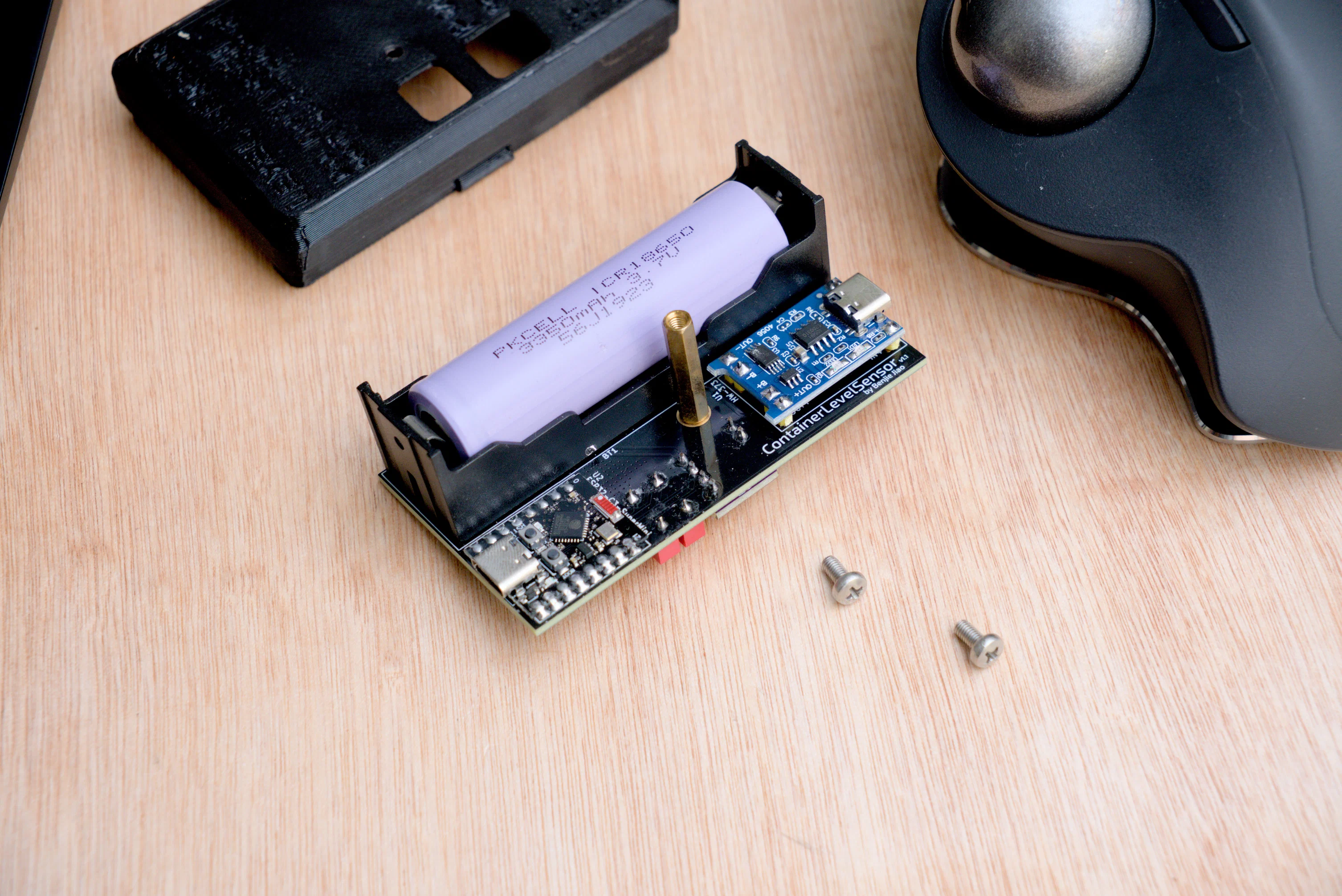
This project uses off-the-shelf modules and development boards for the sensor and power management sections.
Links here are for shops I get them from here in the Philippines, but it shouldn’t be that hard to order anywhere else.
- 1 x ESP32-C3 MCU
- 1 x VL53L0X Sensor
- 1 x HW-373 TP4056-based Charging Module
- 1 x S09 Step Up-Down Power Module
- 1 x 18650 Battery Holder
- 1 x 18650 Lithium-ion Battery
- 1 x M3x22 Female-to-female Spacer
- 1 x M3x6 Female-to-female Spacer
- 1 x M3x6 Bolt
- 1 x M3x12 Bolt (can be longer for thicker container lids)
ESP32-C3 - The main brain of the whole setup. It has built-in WiFi, which allows it to talk to my HomeAssistant server.
VL53L0X Sensor - It can measure up to 2 meters, which was good enough for measuring distances between my container’s lid and the bottom (it was less than a meter tall)
S09 Step Up-Down Power Module was used to regulate my Lithium-ion Battery’s output to a constant 3.3V that the ESP32-C3 requires
HW-373 TP4056-based Charging Module - This gives me battery discharge protection as well as USB-C charging.
18650 Battery Holder and 18650 Lithium-ion Battery - I used the 3500mAh variant, because it’s what I had in stock.
PCB
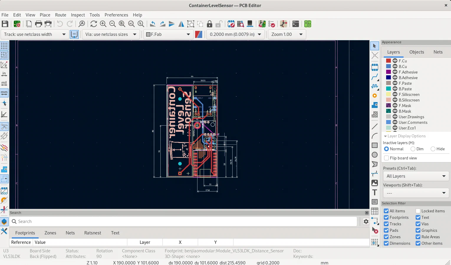
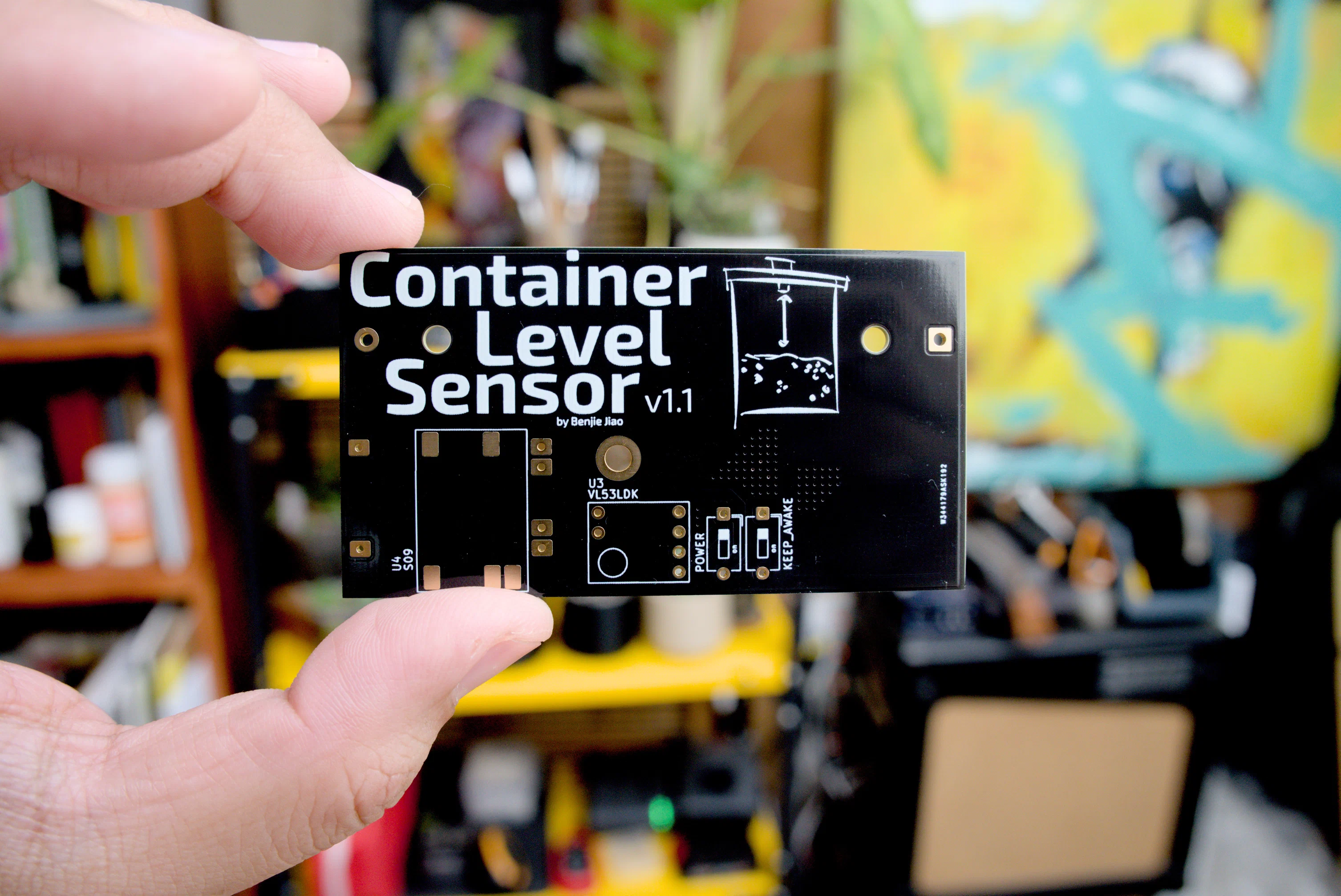
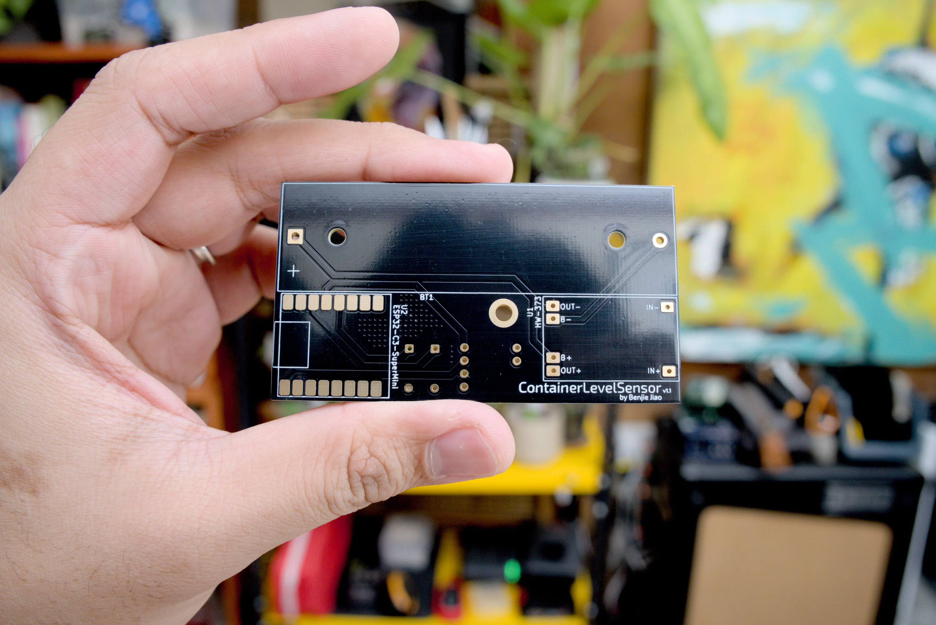
You should be able to assemble this project using just the modules and some wires, but I designed a PCB to help with assembly and reliability.
Sponsorship
The PCBs for this project were sponsored by PCBWay. You can order PCBs for this module directly from PCBWay’s shared project page. Thanks, PCBWay!
Downloads
Enclosure
I also designed the final enclosure using OpenSCAD. This time, I added screw holes to mount the PCBs
Firmware
I used the ESPHome integration in HomeAssistant to program my MCU, which conveniently supports the VL53L0X sensor. The sensor config script can be calibrated to the height of the container through the bottom_distance variable.
sensor:
  - platform: vl53l0x
    id: sensor_distance
    name: "VL53L0x Distance"
    address: 0x29
    long_range: true
    update_interval: 15s

  - platform: template
    name: "Level"
    unit_of_measurement: "%"
    accuracy_decimals: 1
    update_interval: 15s
    lambda: |-
      static float bottom_distance = 0.52;
      static float top_offset = 0.1;
      float dist = id(sensor_distance).state;

      if (isnan(dist)) {
        return NAN;
      }

      float value = 100.0f * (1.0f - (dist - top_offset) / (bottom_distance - top_offset));
      return min(100.0f, max(0.0f, value));
For best results with calibration, mount the sensor in an empty container, check the sensor readings on the logs, and set that as the new bottom_distance value.
Full source can be found on my Github.
Telegram Notifications
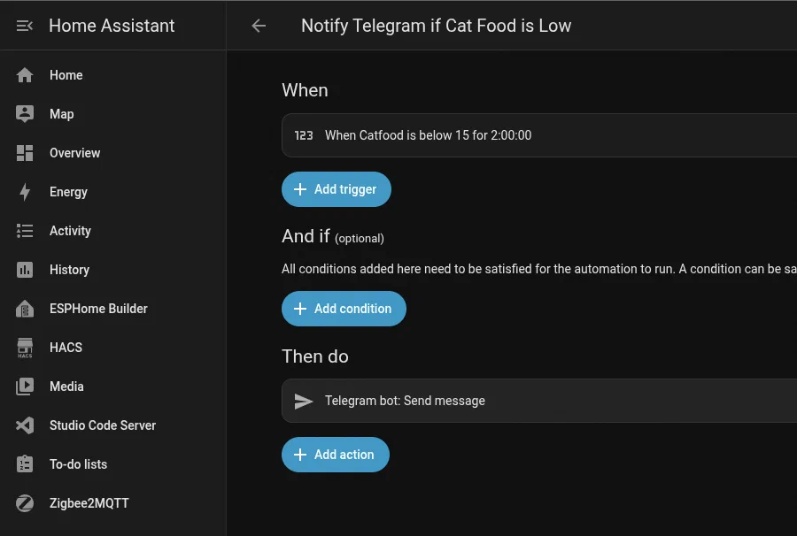
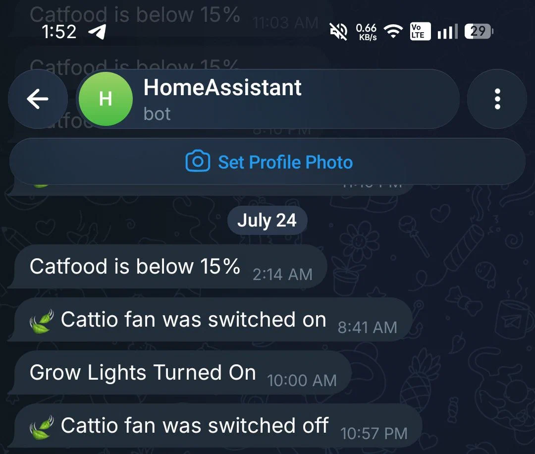
I was easily able to receive Telegram notifications when catfood is below a set threshold using HomeAssistant’s automations section.
What I’d Improve
1. Smaller footprint - The final footprint is still a bit bulky, especially for smaller containers. Maybe future versions can use a coin cell battery, or do away with the off-the shelf modules and use SMT components instead?
2. Lower power consumption - Even with the deep sleep strategy, my prototypes still ran out of batteries after a few months. If there was a way to stretch this out to a year or two that would be great. Maybe try LoRa instead of WiFi?
Conclusion
I’ve managed to run the sensors for a couple of months and they’ve been very useful.
This was my first battery-powered sensor project and I’ve definitely learned a lot. I’m sure there’s so much more to learn from this and I look forward to trying more battery related things in future projects.
As always, everything’s open-source, so you can download all my files and modify/print them as you please.
If you’d like to support what I do, please consider donating through my ko-fi page!